1. INTRODUCTION
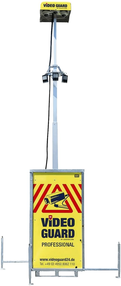
Thank you for choosing VIDEO GUARD from ADDSECURE. VIDEO GUARD is a mobile security and video-supported alarm system for protecting assets, construction sites and perimeters against unauthorized intrusion, vandalism and theft.
+49 (0) 4950 / 8062-110
(8 a.m. – 5 p.m.)
2. TRANSPORTATION OF THE VIDEO GUARD
The VIDEO GUARD may only be moved or transported when it is switched off and the mast is retracted, as otherwise damage to the equipment and the mast cannot be ruled out.
CRANE
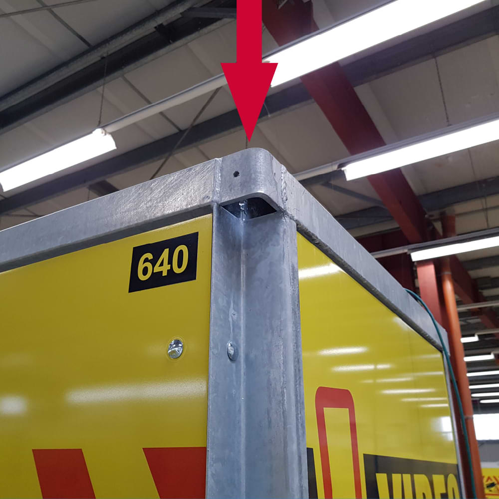
For transportation by crane, lifting eyes are provided in the top four corners for lifting the VIDEO GUARD .
STAPLER
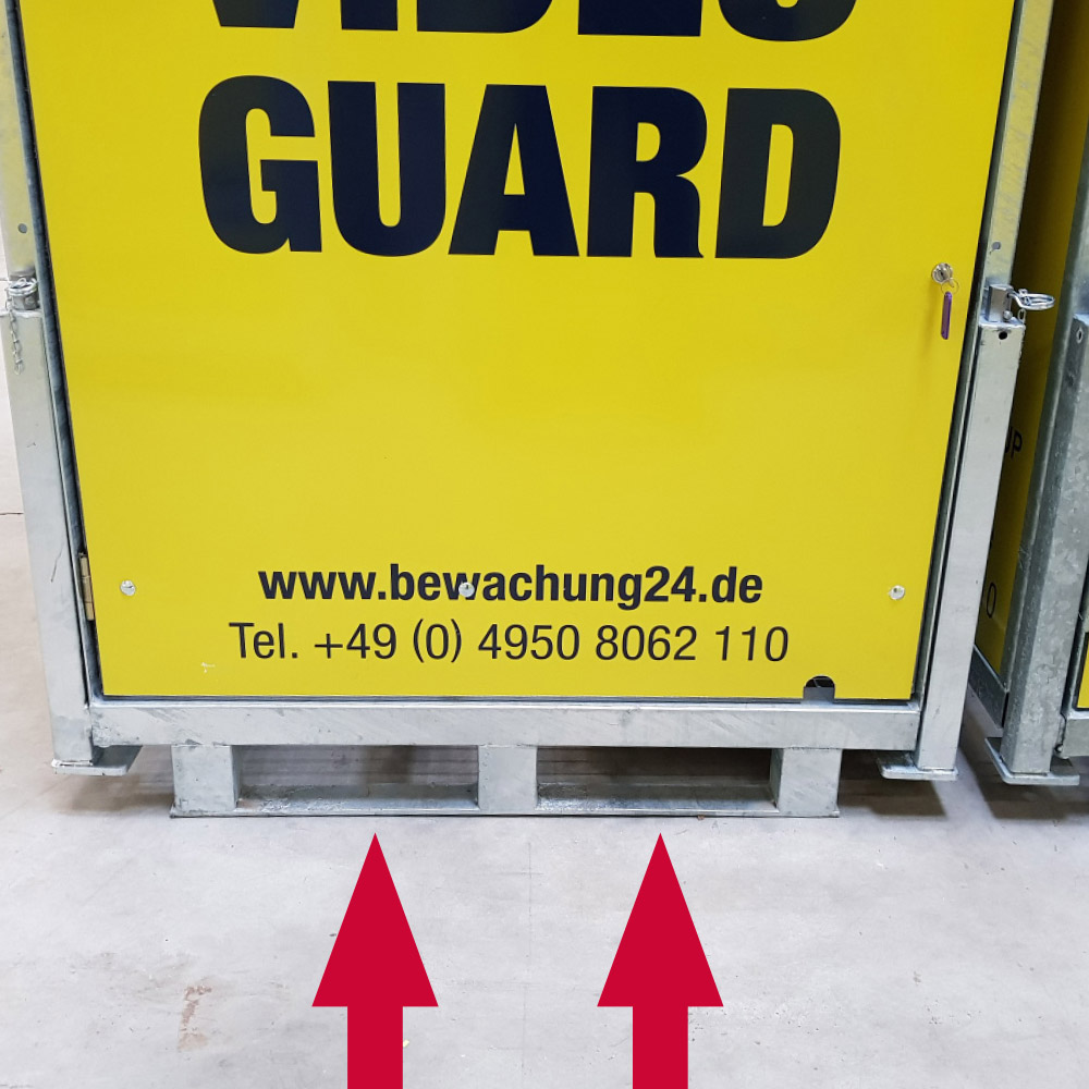
For transport with a forklift and a pallet truck, fork holders are provided at the bottom of the VIDEO GUARD intended. Only use these two options, otherwise the device may be damaged and your safety may be at risk.
Also ensure sufficient transport safety, for example by using additional tensioning straps.
ATTENTION! The VIDEO GUARD weighs 400 kg. Please note the maximum load capacity of your means of transport.
IMPLEMENTING THE VIDEO GUARD
Before moving the VIDEO GUARD, the ISG Service Center must be contacted by calling:
+49 (0) 4950 / 8062-110
(8 a.m. – 5 p.m.)
be informed in order to make the system ready for transportation. Even after relocation, the video analytics need to be technically adapted to the new conditions.
3. SET UP VIDEO GUARD
Align the system with the door facing the area to be monitored.
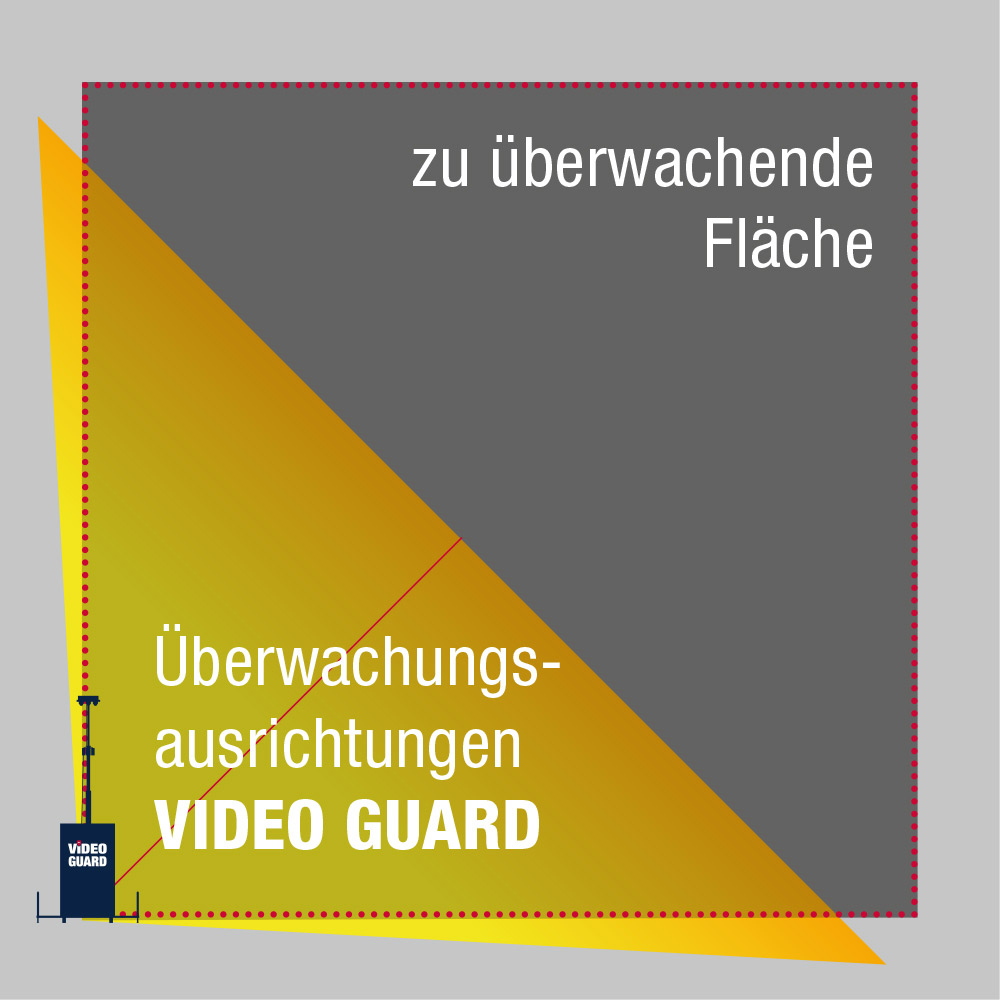
Pull out all 4 support legs completely.
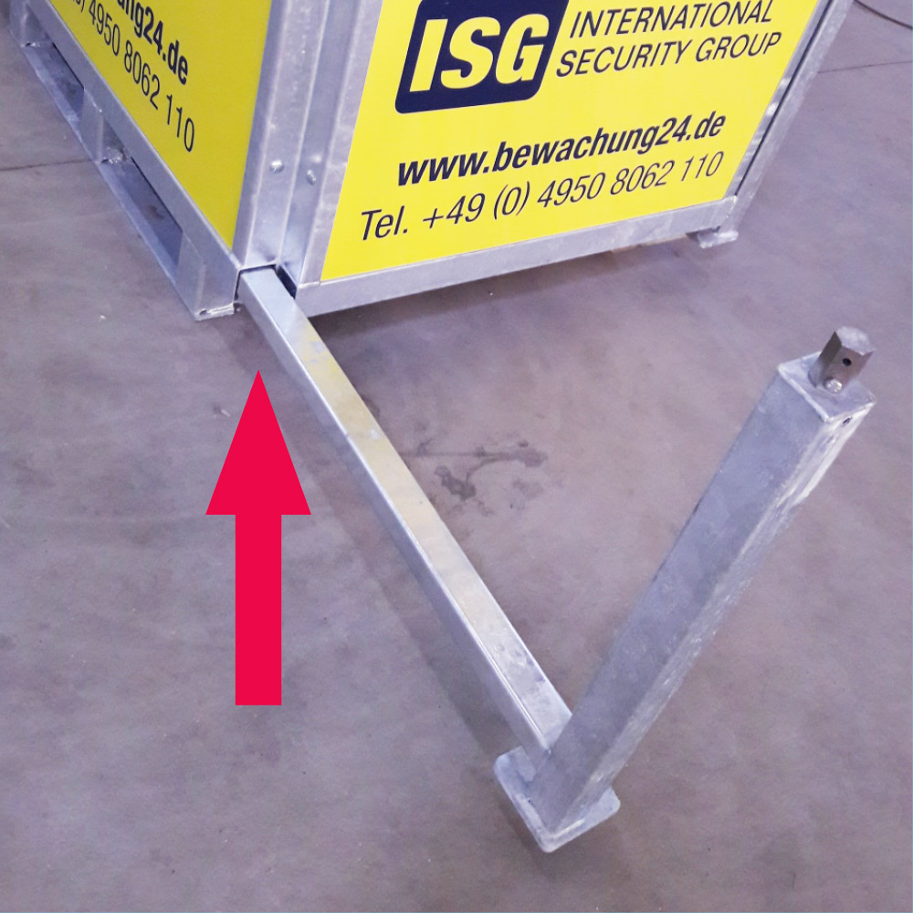
Lower the feet with a 24 mm open-end wrench.
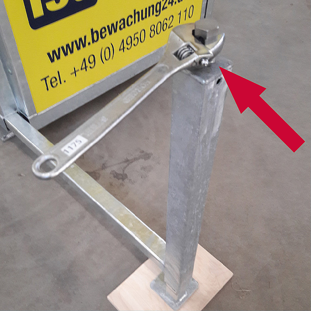
Level the system with your feet.
IMPORTANT: Check the substrate after heavy rainfall. The support legs must not sink into the ground.
4. CONNECT THE VIDEO GUARD TO THE POWER SUPPLY
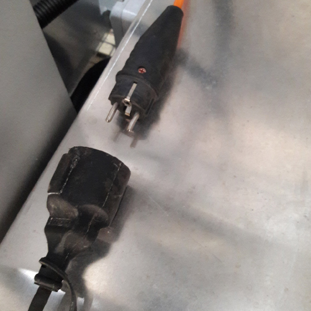
Connect the socket of the customer’s power supply to the plug of the VIDEO GUARD.
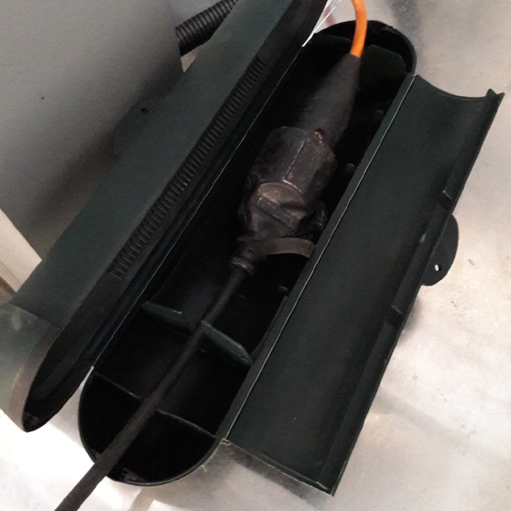
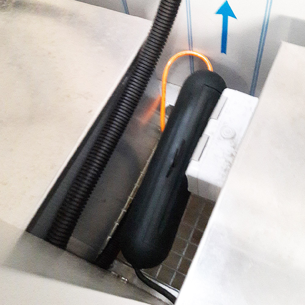
OR
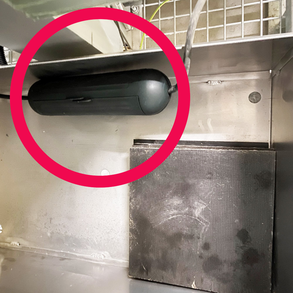
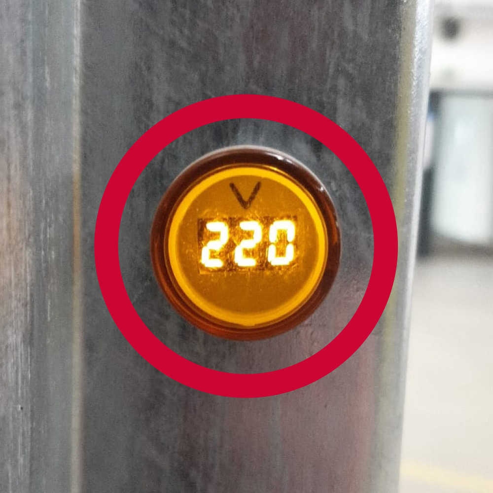
The system is properly supplied with power when the voltmeter on the housing indicates 220 V. Level the system with your feet.
5. ALIGN VIDEO GUARD CAMERAS
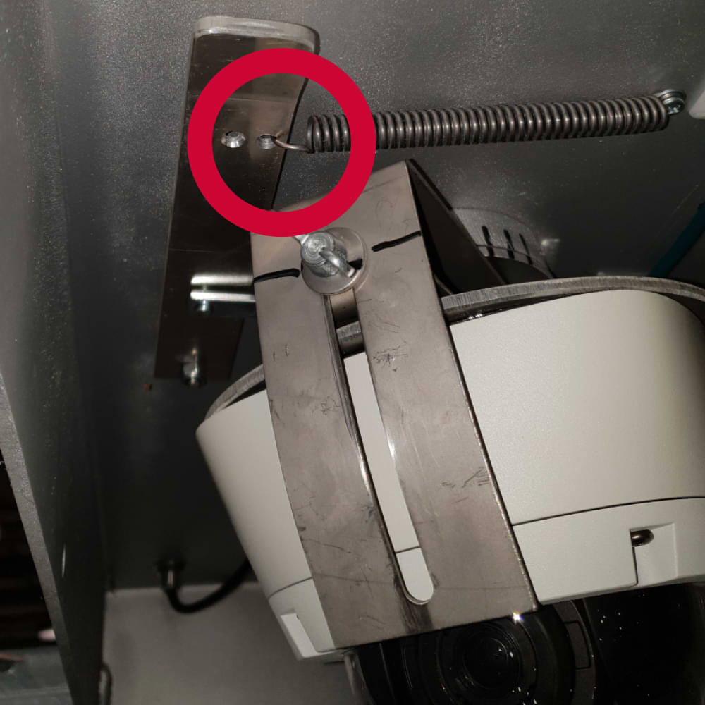
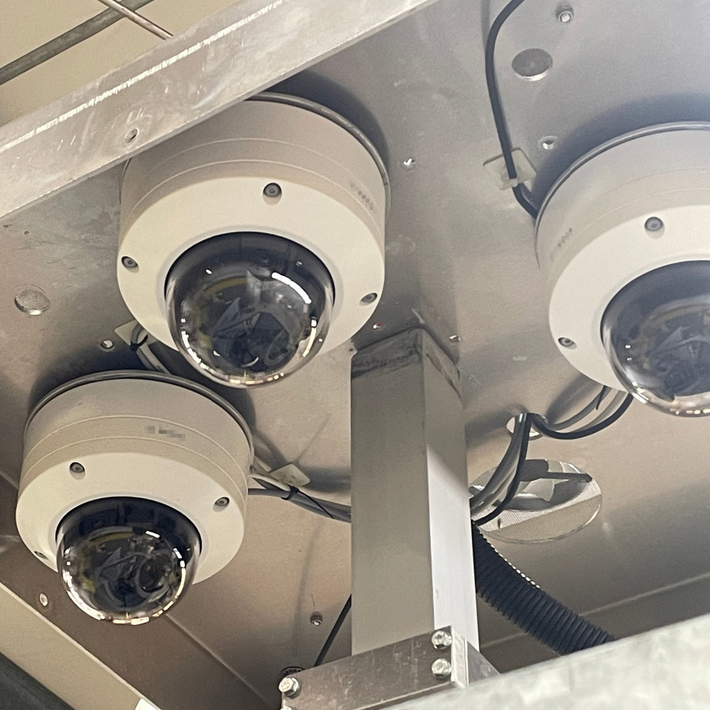
To turn the camera, pull the cock and turn the camera with the turntable. Release the clamping tap to lock it in the new position.
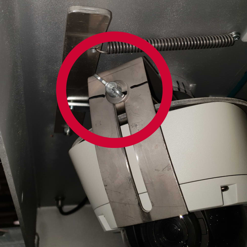
To tilt the camera, loosen the wing screw, tilt the camera mount to the desired position and retighten the wing screw.
These are as follows:
+49 (0) 4950 / 8062-43
(8 a.m. – 5 p.m.)
6. ALIGNING THE VIDEO GUARD INFRARED SPOTLIGHT
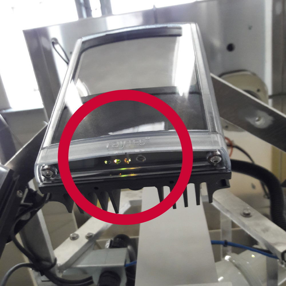
If the cameras have been adjusted, the infrared spotlights must be aligned accordingly.
Loosen the wing nut of the infrared headlights.
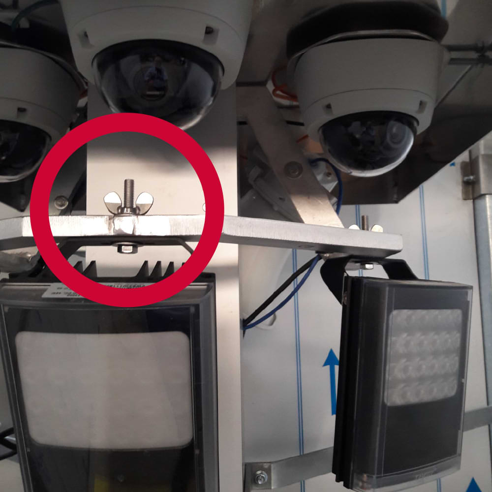
Align the infrared spotlight in the viewing direction of the camera lens.
Tighten the wing nut of the infrared spotlight hand-tight.
IMPORTANT: The infrared spotlights must point in the same direction as the camera lens.
Please note that reflective material (barriers / warning markings) can interfere with the camera image. If possible, these must be removed from the monitored area.
7. VIDEO GUARD EXTEND MAST
Turn the mast crank clockwise and raise the mast as far as it will go.
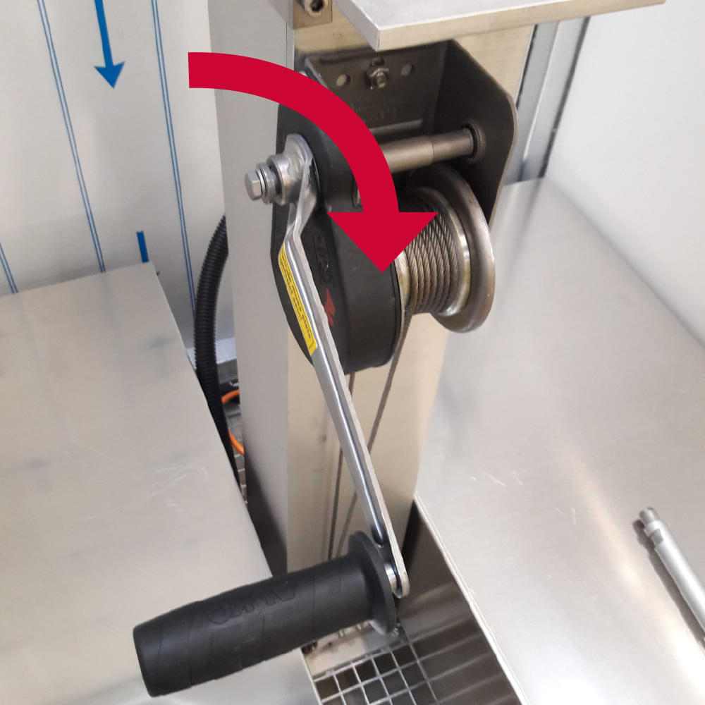
Pay attention to the routing of the cable conduit so that it does not get caught and torn off.
Insert the safety bolt (left battery box) with the notch facing upwards into the hole on the side of the mast.
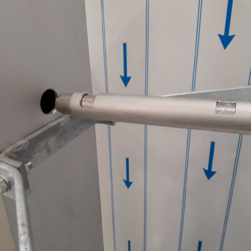
Crank the mast down slightly so that it rests on the safety bolt and is relieved.
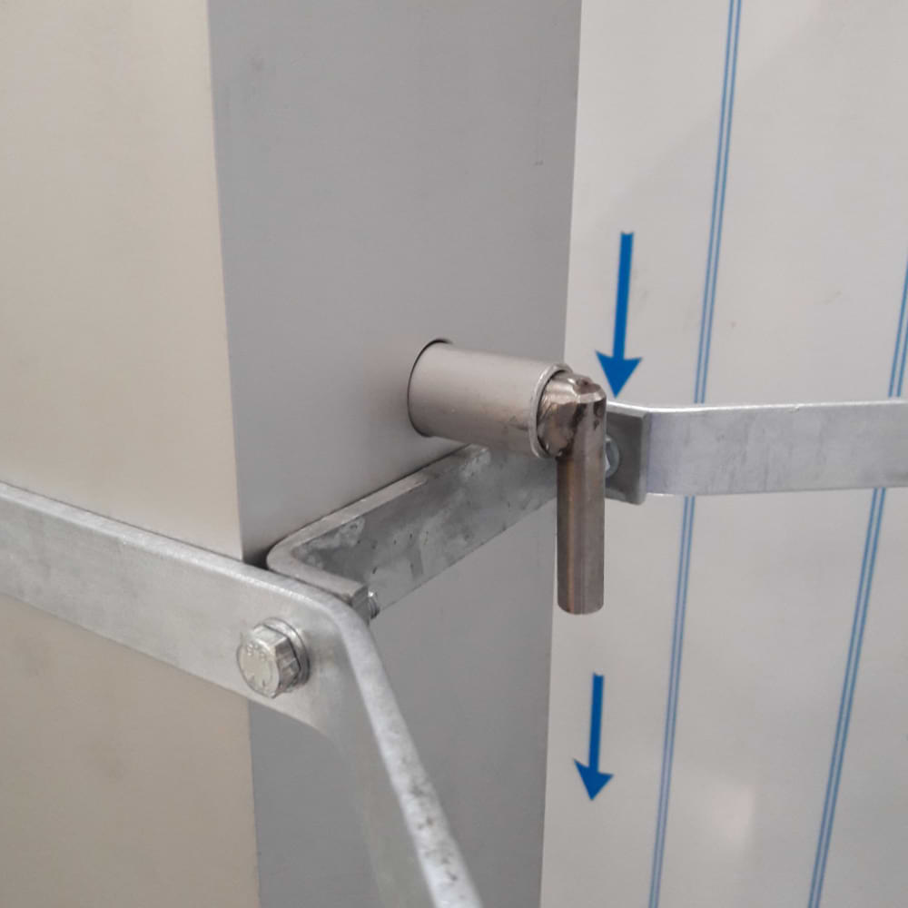
IMPORTANT: From wind force 8, the mast must be retracted for safety reasons.
In the event of faults or blockages on the mast, please contact ISG by telephone. Please do not attempt to carry out any repairs yourself.
8. VIDEO GUARD TURN ON
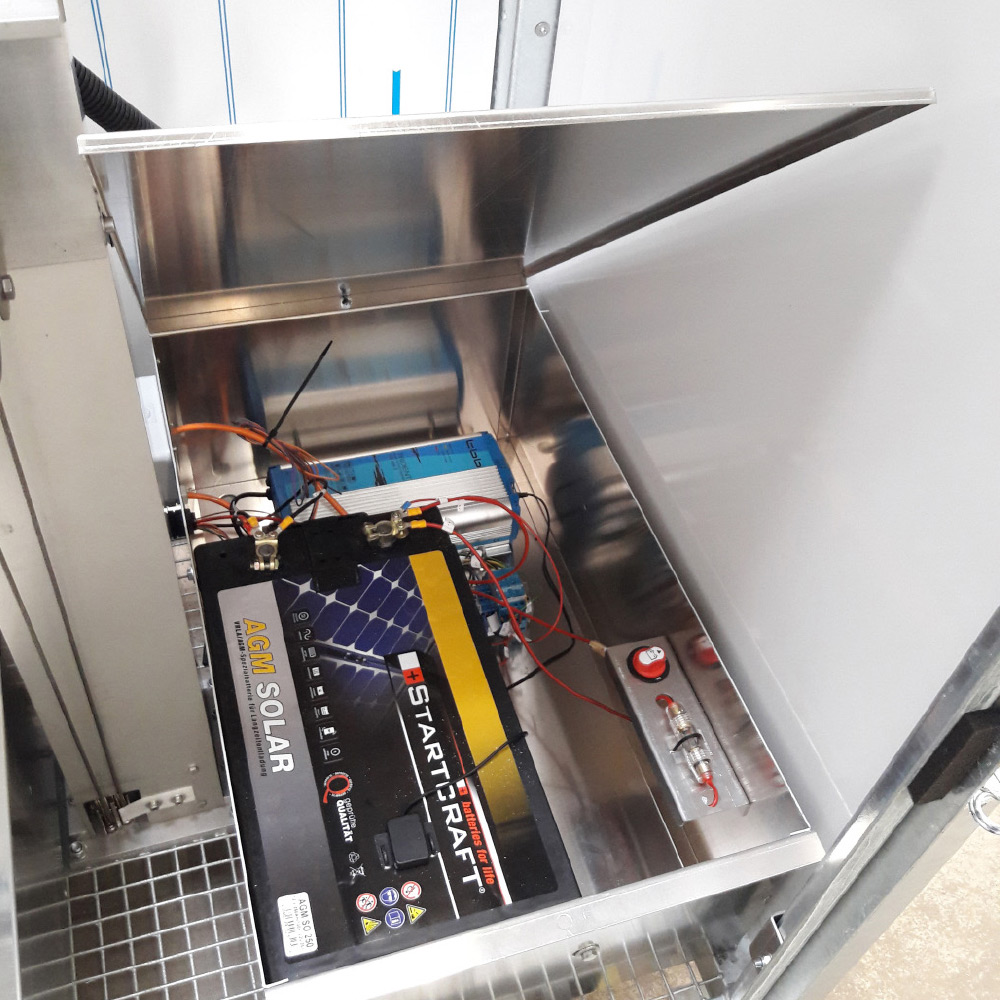
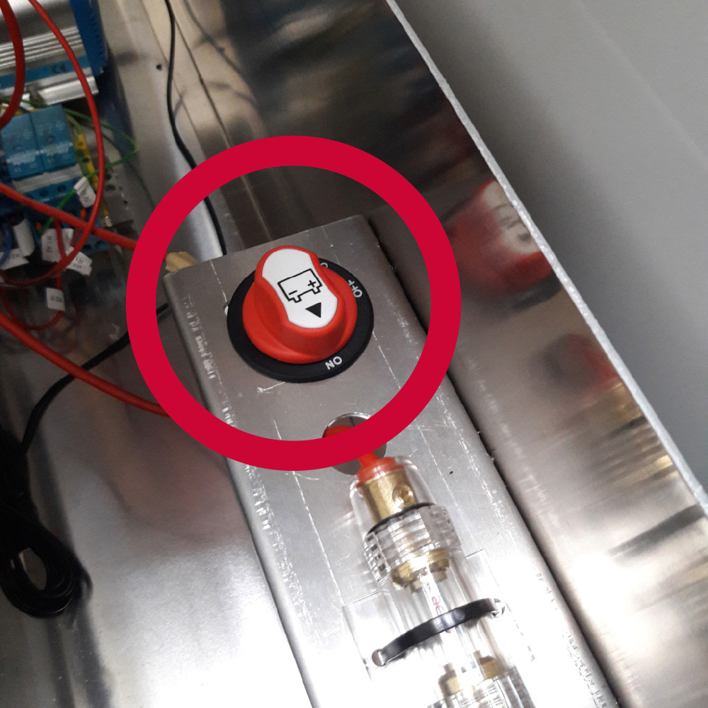
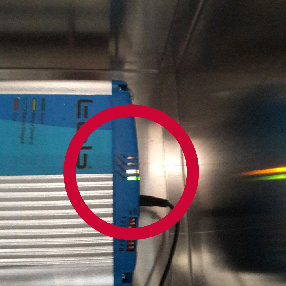
ALTERNATIVE 1 WITH CHARGER
Lift the cover of the right-hand battery box.
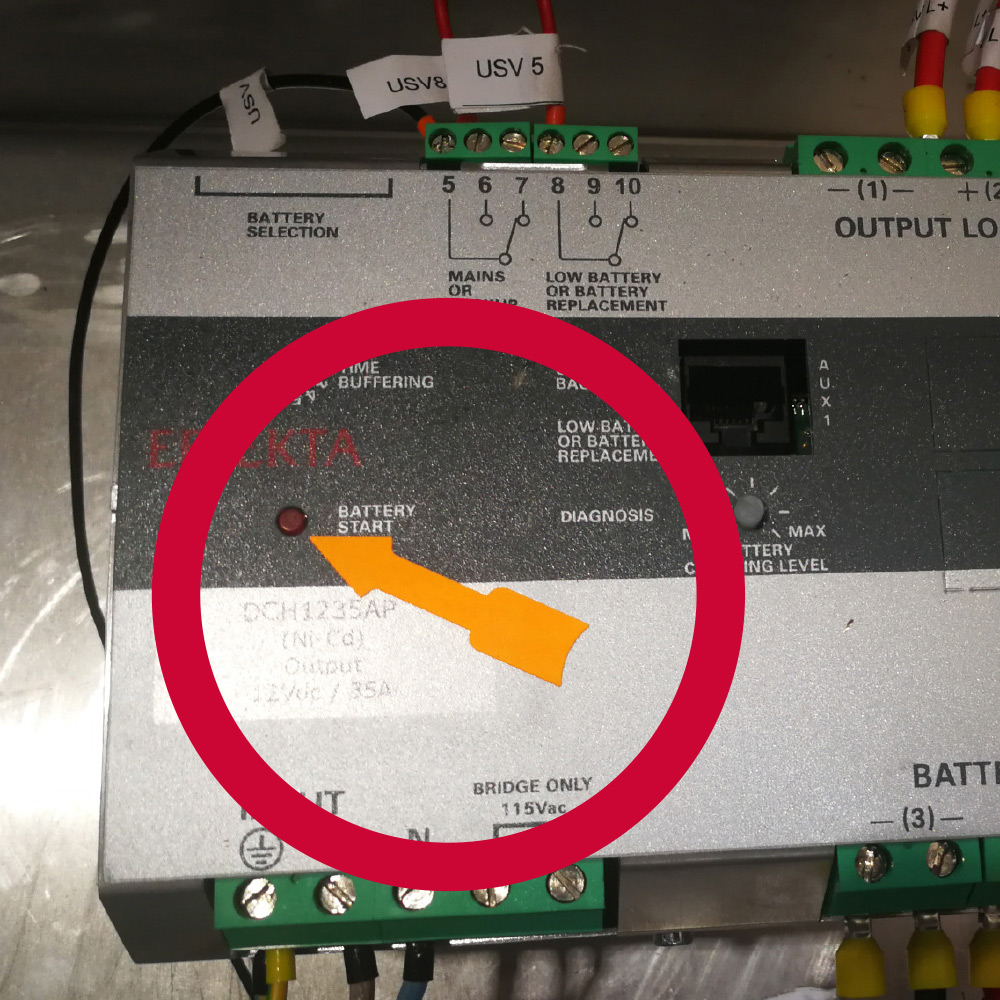
ALTERNATIVE 2 WITH USV
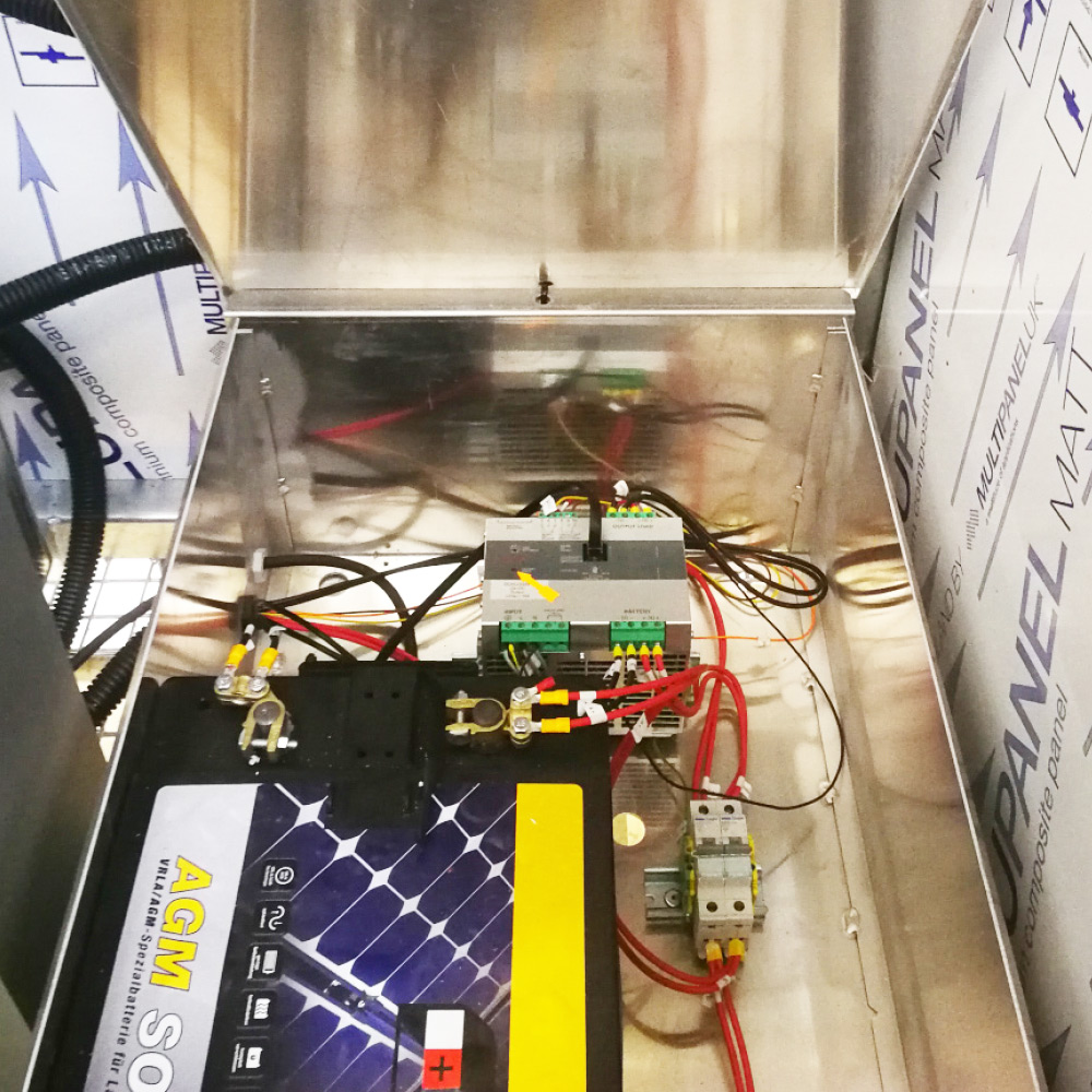
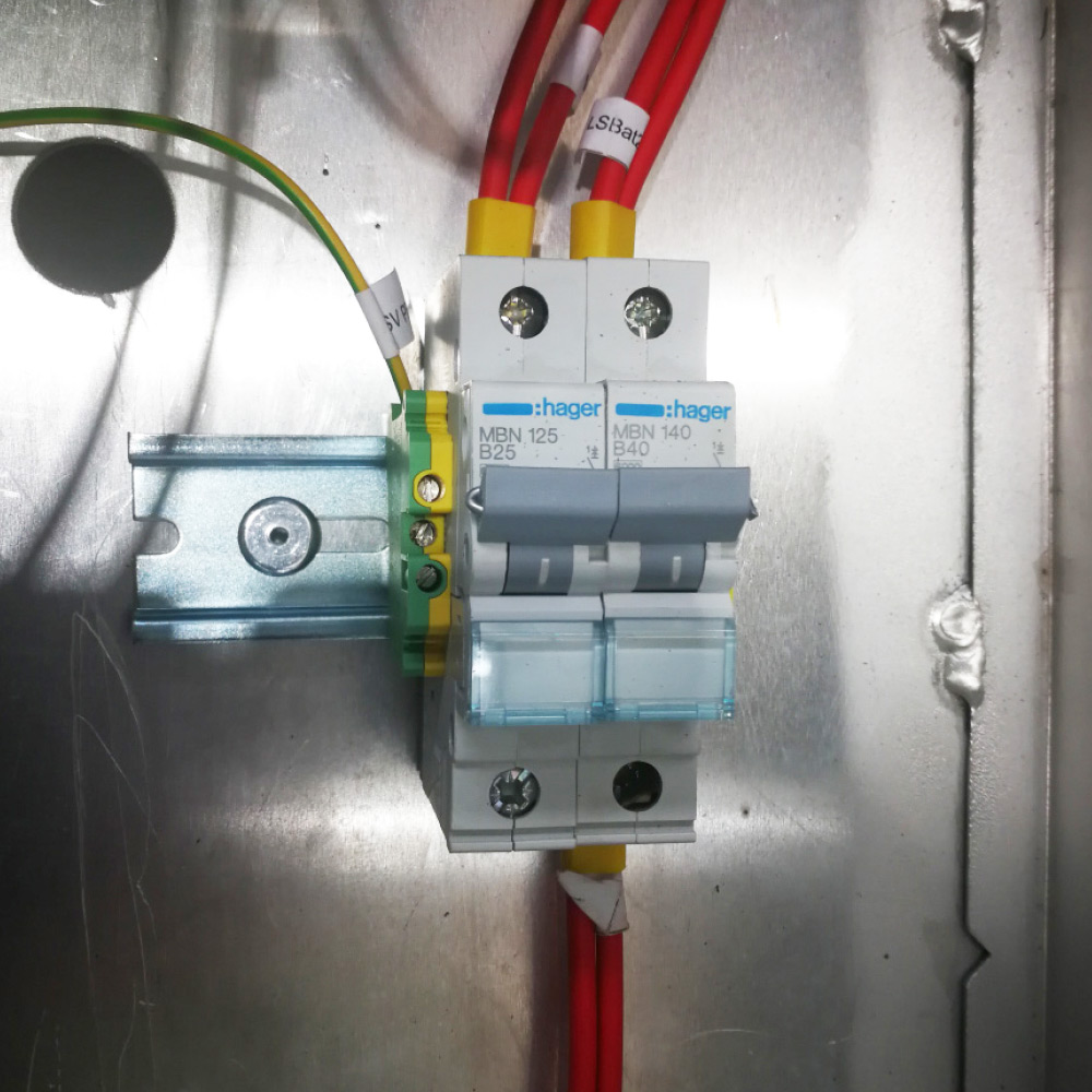
(UPS = uninterruptible power supply)
Lift the cover of the right-hand battery box.

9. CHECKLIST VIDEO GUARD STRUCTURE
You are currently viewing a placeholder content from YouTube. To access the actual content, click the button below. Please note that doing so will share data with third-party providers.
More Information10. SET UP VIDEO GUARD SOFTWARE
To set up the analytics software, please contact our technicians by telephone:
+49 (0) 4950 / 8062-34
(8 a.m. – 5 p.m.)
IMPORTANT: If the VIDEO GUARD or the cameras have been adjusted or rotated, the ISG Technical Service Center must be contacted for an adjustment of the analytical procedure (setup).

